Performance Indicators
The different sets of requirements in Industrial Automation caused manufacturers to develop many different protocol stacks efficiently summed up in IEC 61784 in the different PCFs defined in the standard.
CPFs define a structure which is technology based. However IEC 61784-2 facilitates the choice of the proper CP by defining a set of Performance Indicators with the purpose of rating the different CPs under specific perfromance-related quantities.
Every PI has limits and ranges defined in the context of certain conditions, PIs are also connected together by a network of relationships. The use of PIs is supposed to facilitate the detection of the proper CP to be used in a factory or industrial environment which has specific requirements. Here we will consider the most common PI categories:
User application requirements
PIs can provide a good way for selecting the CP which fits the most a certain set of requirements. However requirements have some very common profiles, so CPs are grouped into different categories by the range of values of some PIs, the most common is based on delivery time:
Data capacity PIs
CPs can be categorized basing on transmission capabilites. We find 3 very common PIs targeting this performance measure.
Delivery time
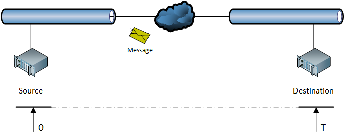
This PI measures the time needed to convey a Service Data Unit (payload of message) from a source node to a destination node. The measurement is performed at Application level, thus the value includes all overheads introduced by the intermediate protocols in the stack.
The standard defines 2 flavors for this PI:
- Best case scenario The delivery time is measured in case no transmission error occurs.
- Lost frame The delivery time is measured in case one frame is lost, thus retransmission is included in the value.
Throughput RTE
Throughput , expressed in byte/s, of total amount of application data on one single link. If the network defines more links, this PI has to be expressed for each one of them.
Non-RTE Bandwidth
This is the percentage of bandwidth which can be utilized for non real time traffic. This PI is related to the previous one by the following equation:
As it is possible to see, to relate to the Throughput RTE and the total bandwodth , we subtract from the latter the fraction of bandwidth occupied by (converted into bit/s as is expressed in such a way) and the fraction of bandwidth taken by overhead traffic (control frames for example).
Timing PIs
This is a set of PIs measuring the performance of protocols from the point of view of synchronization.
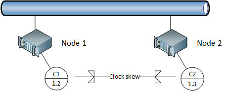
Time synchronization accuracy
Some protocols require clock synchronization among different devices. We will see, for example, that Profinet IO requires all IEEE 802.3 switches to be clock synchronized.
In order to measure how well synchronization is performed, this PI will measure the maximum deviation (skew) between the clocks of any pair of nodes in the network (requiring clock synchronization).
Non-time-based synchronization accuracy
This PI measures the maximum jitter (jitter can be interpreted as displacement from mean value: Variance or Standard Deviation) of the cyclic behavior of any pair of nodes in the network.
In the CPs defined in IEC 61784, we often have the implementation of a TDMA. In this context, one arbitrator node defines data transmission cycles for the different controlled stastions. Every node will emit, in this context, cyclic traffic (frames); however when examining many periodic transmissions, it is possible to experience variations on the transmission instant inside every period: the jitter over the difference of this quantity measured on the same clock cycle between 2 nodes is represented by this PI.
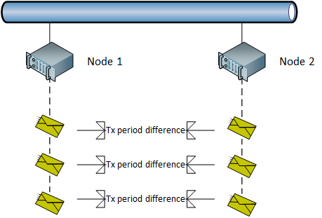
This PI provides an indication over how accurately different nodes are synchronized on the same time-slot when transmitting cyclic traffic (traffic to be scheduled under the context of a TDMA scheduling system). Usually jitter is expressed as an RMS.
The reason why it is called "Non time based" is because it is not measured in terms of clock skew, but in terms of the behavior of cyclic events (cyclic traffic).
Redundancy recovery time
This PI is related to failure recovery and it measures the maximum amount of time required for the network to become fully operational after an internal failure.
Topology PIs
This category includes PIs related to the topology of the network and its structure.
Number of RTE end-stations
It measures the maximum number of real time nodes (stations generating real time traffic) supported by the network. Note that we only take into consideration end-stations, it means that switches or other commuting devices are not included.
This PI is typically associated to a CP in IEC 61784.
Basic network topology
Indicates the topology supported by a network. We can have these possible topologies:
- Hierarchical star
- Ring
- Daisy-chain
- A combination of any of the previous
This PI is typically associated to a CP in IEC 61784.
Number of switches between RTE end-stations
This PI defines a range for the number of supported switches in a network.
Since switches introduce delay due to address evaluation (remember that switches are not hubs, they deliver a frame on a specific port basing on the destination MAC address), it is important to understand how much of this overhead is supported by a protocol stack so that a network can successfully observe time criticalities.
This PI is typically associated to a CP in IEC 61784.
Relation to delivery time
There is a connection between the delivery time PI and all topology PIs we have introduced so far.
Take for example the delivery time and the number of switches in the network. It is not possible to define both independently as they are related to each other. The more switches we add, the more delay we introduce, thus the higher will the delivery time be!
Another example is the topology. A ring vs a daisy chain is an important choice to make and it impacts the delivery time. A ring topology cuts in half the delivery time compared to a daisy chain in the worst case scenario.
So, when customizing a network, it is important to calculate the delivery time from topology PIs.
The delivery time PI is used to define 3 different classes of CPs supporting 3 different time demanding contexts:
Low speed class
Also labeled as Human Control, considers CPs whose delivery times are around . The name suggests that this class of CPs are typical of systems where humans are involved for observation, monitoring and supervision.
The human eye can easily perceive differences which occur with a period of , if a picture where to be shown for a period of time , we would have an image processing rate of , or equivalently, of , which is fine.
Applications Typical applications span across process automation and building control.
Infrastructure CPs which simply deploy TCP/IP commuication channels without any modifications are just fine and can handle the low requirements in time very well. Realization on Top of TCP/IP can support this class.
Process control class
This class includes CPs which can guarantee delivery times below .
Applications This class is typical of most tooling machines and is also utilized in machine control systems, PLCs and PC-based control systems.
Infrastructure To guarantee the delivery, it is sufficient to act on the protocol stack in order to differentiate the handling of non-real-time traffic from real-time one. By doing so, teal-time traffic will bypass TCP/IP and immediately reach the Ethernet lower layers, thus guaranteeing better delivery time and less jitter. Realization on Top of Ethernet can support this class.
Motion control class
The strictest class of CPs requires delivery time around and a jitter of no more than . So, as it is possible to assess, we also have requirements for periodic traffic.
Applications CPs into this class are typically utilized motion control where time constraints reach highly demanding levels. Considering the requirement on jitter, time slotted approaches like TDMA are often deployed.
Infrastructure It is not possible to rely on TCP\IP, thus a solution modifying the Ethernet layers is required. Minimal throughput to be guaranteed is 100 Mbit/s (Fast Ethernet can be considered). It ight also be necessary to apply modification to hardware and to medium access strategies. Realization Modified Ethernet is the only possible option for supporting this class.
Overview
An overview of the classes is provided in the following table:
| Class | Name | Applications | Realization | ||
|---|---|---|---|---|---|
| Class 1 | Low speed | N/A | Human control | On Top of TCP/IP | |
| Class 2 | Process control | N/A | PLC, PC-control | On Top of Ethernet | |
| Class 3 | Motion control | Motion control | Modified Ethernet |