Ethernet PowerLink
EPL is a protocol defined by Bernecker & Rainer (B&R). Now the protocol is also part of a standardization group.
This protocol stack is defined as CP 13/1 in IEC 61784-2.
Class EPL fulfills the requirements for Class 2 in IEC 61784.
Nertwork structure
EPL defines the following pillars in its architecture:
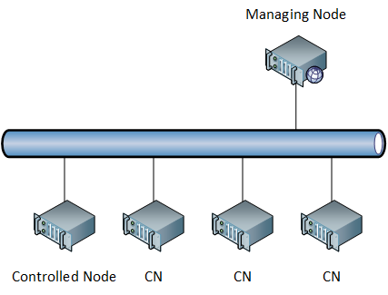
- Master/slave scheduling One single node called Managing Node or MN schedule all transmissions and is the only active station which can autonomously decide to initiate a communication on the channel.
- Time-slotted scheduling Time is divided into time slots, thus a TDMA is deployed.
- Shared Ethernet segment All stations are connected to a shared bus link managed by the MN. Also, all communications are acked (since Ethernet is used).

This communication system is called: Slot Communication Network Management.
Transmission scheduling
The MN acts like a bus arbitrator. All other stations on the shared segment are called Controlled Nodes (or CN) and they can only initiate a transmission upon request by the MN.
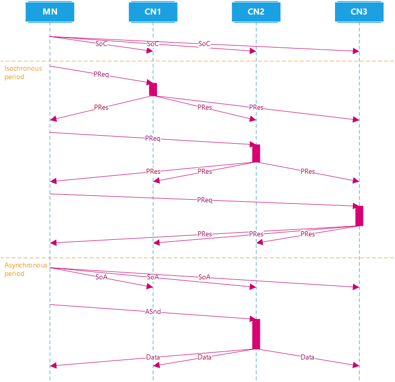
Since we have TDMA, synchronization of clocks is necessary in this CP. So all stations are clock-synchronized. The MN signals all CNs the beginning of new communication cycle by broadcasting a Start-Of-Cycle (or SoC) frame.
Real-time vs non-real-time traffic The MN ensures that real-time traffic is scheduled in a cyclic phase where it polls every station for transmission and, if one was requested, grants it; on the other hand, non-real-time traffic is handled afterwards in later time slots reserved for non-real-time data.
Traffic types EPL recognizes 2 types of traffic:
- Cyclic data: This is the real time traffic.
- Acyclic data: This is non-real-time traffic.
Important Note that terms cyclic and acyclic have nothing to do to periodic and aperiodic real time traffic.
If a node is able to send cyclic and acyclic traffic, then it must employ EPL. Otherwise, if only non-real-time traffic is sent, that node is not required to employ EPL, in that case it must be deployed according to EPL network protection specification.
Scheduling cycles
Every communication cycle, referred to as: Isochronous EPL Cycle, is divided into 4 different periods:
- Start period Lasts the time needed to convey the SoC frame (sent in broadcast) to all stations in the shared segment. This period duration should not vary, its duration is extremely connected to the SoC frame which, therefore, has very strict requirements in terms of delivery time and jitter.
- Isochronous period Here the MN sends unicast poll request frames to every CN in their respective time slots (defined and handled by the MN itself). Real time traffic is scheduled here.
- Asynchronous period Non-cyclic data transmissions are allowed, always supervised by the MN. Here non-real-time traffic is scheduled.
- Additional idle period An idle time frame necessary to guarantee synchronization before starting an new cycle.
MN polling In the isochronous period, the MN sends (unicast) a Poll-Request (or PReq) frame to every CN. If the polled CN has something to send, it will send a broacast Poll-Response (or PRes) frame on the shared segment. Real time data can flow from one CN to other stations in this way.
Multiplexed devices During the isoschronous period, also multiplexed devices are polled. Multiplexed devices are devices which are not polled during every cycle as they share the same time slot with some other device.
Acyclic traffic
The asynchronous period is used to transmit non-real-time traffic. To signal all CNs that this period has started, a Start-Of-Asynchronous (or SoA) message is sent broadcast by the MN.
Here, time is still slotted and the MN grants access to the shared segment to one single CN or to itself in order to transmit one single asynchronous message only.
How does the MN know which CN has acyclic data to transmit? During the isoschronous period, that CN was supposed to send that information in its PRes after being polled by the MN.
Important EPL prefers using UDP/IP for asynchronous messages.

The previous picture provides a good overview of a simple cycle where one MN handles 3 CNs.
Network design
EPL allows the possibility to connect to the network EPL and non-EPL devices. Of course, non-EPL nodes will use TCP/IP and Ethernet. However this possibility comes with a limitation:
It is not possible to have EPL nodes and non-EPL nodes cohexist on the same shared segment.
The limitation comes from the fact that non-EPL nodes, which do not use the EPL upper protocols, will currupt the bus arbitration performed by the MN! Since these nodes have no knowledge of EPL, they will not observe the time slotting performed by the MN.
However, EPL nodes can perfectly operate as normal Ethernet devices.
EPL network protection
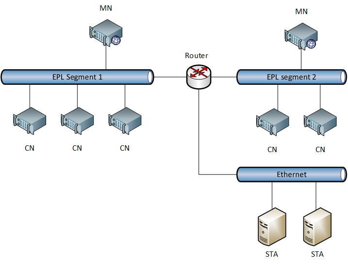
In order to overcome this issue, we must avoid mixing EPL and non-EPL devices on the same shared segment. Thus the network is split into more segments by a router or a bridge, thus making the EPL segment a protected Ethernet.
The protocol supports the possibility to actually structure the network into multiple protected segments, each one of them having one MN as bus arbitrator. Those MNs will communicate to each other thanks to a distributed clock synchronization mechanism implemented in IEEE 1588.
Also, every MN incorporates IP routing functionality in order to communicate with other EPL segments and also non-EPL segments. This allows an EPL network to scale and extend.

The picture shows a generic network with protected EPL segments.
Other characteristics
EPL does not employ switches for collision avoidance. This mechanism is already guaranteed by the MN. However it is possible to build the shared segment by means of hubs. It is possible to deploy up to 10 hubs by cascading them, by exceeding this limit, requirements on delivery time and jitter might be compromised.
Also, switches though not recommended, are actually not prohibited by EPL. However it would be meaningless to use them considering that the MN does the job!
Application Layer EPL uses CANopen as application layer.
Performance Indicators
IEC 61784-2 defines 2 CPs for EPL:
- 13/1a For small sized automation systems.
- 13/1b For large sized automation systems.