Error frame
The structure of an error frame is different:
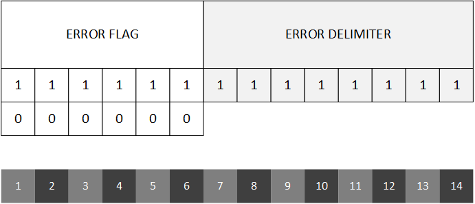
- Error flag This field is 6 bits and is used to mark the type of error. This field is not subjected to bit stuffing.
- Active Error Flag All dominant (
000000). Note that, since purposely not stuffed, this sequence of bits will generate an error on the bus. - Passive Error Flag All recessive (
111111). This sequence is passive on the bus as it merges in the idle time.
- Active Error Flag All dominant (
- Error delimiter This field is always 8 bits long and is always recessive (
11111111).
This frame is special as it is not sent as a whole, but in two different stages. Nodes typically send the Error flag first, and then, after a certain time, they will send the Error delimiter.
Error states
Every node keeps 2 error counters:
- Receiver Error Counter (REC)
- Transmit Error Counter (TEC)
Both counters start with a value of 0 and they get incremented/decremented depending on the node's behavior. The higher the value of one of these counters, the worse is the efficiency of the node.
Every node can have 3 error states basing on the values of these 2 counters. Its behavior, error-wise, depends on its current state:
| State name | Condition | Capabilities | Error flag |
|---|---|---|---|
| Error-Active | Takes part in communications | Active Error Flag | |
| Error-Passive | Takes part in communications (8 bit delay) | Passive Error Flag | |
| Bus-Off | Cannot transmit but can receive | N/A |
The last column indicates what Error flag the node will send on the bus in case it detects an error. Depending on it scurrent state, it might send an Active Error Flag or a Passive Error Flag.
Active Error Flag
When a node encounters an error condition and is in Error-Active state, it transmits an Active Error Flag on the bus.
Since this error flag (purposely) violates the bit stuffing condition, all nodes on the bus will react in a chain reaction by also sending an Error flag (according to the last column of the table) or nothing if it is in the Bus-Off state. So a chain reaction will occur notifying all the other nodes that something has happened.
Bus error flag occupation
As soon as an Active Error Flag is sent out, a chain reaction will occur. The bus will possibly start being occupied by dominant bits if nodes are operating in normal conditions. Every node who sent an Error flag, will wait for the bus to present a recessive bit in order to start senidng the Error delimiter. Remember that the bus always performs an AND arbitration, so even if Passive Error Flags are sent, they might be overriden by Active Error Flags, it means that it will take some time before the bus gets free (back to idle) again.
The condition for having 1 recessive bit is needed before sending the delimiter in order to wait for all stations to send their Error flags. Once the bus is free, all stations will transmit the delimiter (which is basically an 8 bit long idle time) after which the bus will get back to its normal operative state.
Passive Error Flag
When a node in Error-Passive state encounters a problem, it will send a Passive Error Flag. However, since this flag is all recesive, nobody will hear it and nodes will not react, The chain effect will not occur.
In case of Bus-Off
When a node is in Bus-Off state it is not able to transmit. When it encounters an error the only thing it can do is incrementing its internal counters. When such a state keeps persisting after a certain amount of time, the node might be declared hopeless, thus requiring, worst case scenario, a manual reset after a complete exclusion from the network.
However a resuscitation is possible. If both the error counters get decremented and go down below the 256 threshold, the node will go back in the bus.